
Dual Systems -- 68000 CPU Board
Dual systems based their business on the Motorola 68000
line of CPU's. I am looking for a better image of this board.
If you have one please let me know.
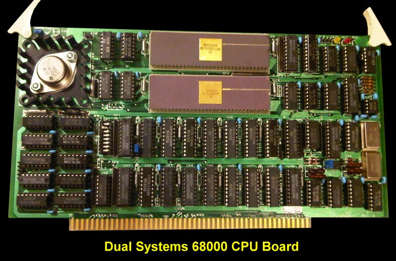
The board ran with a 8MHz clock and could address up to
16MG of RAM address space (24 bits). It met all IEEE-696 S-100
bus specifications. No wait states were requires for 4Mhz type RAM boards.
They had a second board called the CPU-68000M which also ran at 8MHz but
also included the Motorola MC68451 Memory management Unit LSI chip.
This allowed sophisticated segmented memory management. There was also
a CPU-68000M-L10 which was identical but ran at 10MHz.
There were onboard 3 LED's. RUN (green), HALT (red) and HOLD (yellow).
As per the IEEE-696 specs the phantom lime could be put on the bus during
power on.
Port IO addressing and the 68000.
The 68000 instruction set does not have an explicit Input/Output
instruction. Motorola architects intended for all 68000 I/0 to be memory
mapped. Memory mapped I/0 takes advantage of the many powerful addressing
modes of the 68000 for fast, efficient I/0 routines.
To support S-100 I/0 mapped peripherals and to allow communication between
the 68000 and the 68151, Dual dedicated a 64 kilobyte page of the address
space for I/0 and the MMU registers. This page could be based in the
physical memory space at one of two following addresses:
I/0-MMU page:- 1) 7F0000 to 7FFFFF
(L0)
2) FFOOOO to FFFFFF (HI)
The jumper which selected the location of the physical base address for the
I/0-MMU page has two settings: HI and L0. The HI and L0 jumpers refed
to the position of the I/0-MMU page at either a HI (FFOOOO) or L0 (7FO00O)
base address. The CPO/68000/M came configured with the I/0-MMU page jumper
set to the L0 position. Any access by the CPU/68O00/M to that I/0 page
caused the appropriate I/0 status signals to be asserted on the S-100 bus.
The MMU registers resided in the top 64 bytes of the I/0-MMU page, from
7FFFC0 to 7FFFFF, or FFFFC0 to FFFFFF in physical memory, depending on where
the I/0-MMU page was located. On any access to the MMU registers, all S-100
strobes are rescinded until the data transfer between the CPU and the MMU
was complete. Transfers between the 68000 and the MMU occur at 8 MHz.
For Example:-
If the I/0 page jumper was set to the HI position, the I/0 page base address
is FF0000H. Hex address FF0002
corresponds to I/0 port address 2. So the
68000 instruction:-
M0VE.B OFF0002H, DO
is functionally equivalent to the 8080 instruction
IN 02H
The manual for this board may be
obtained
here.
Other Dual Systems
S-100 Boards
68000 CPU
256K RAM
Clock Board
CMEM-RAM
Digital-to-Analog
Analog-to Digital
4SIO
EPROM
This page was last modified
on
06/10/2011